Lasers
Lasers are used in ACQ4 for photostimulation and scanning laser imaging, usually in conjuction with a Scanner device. Lasers provide:
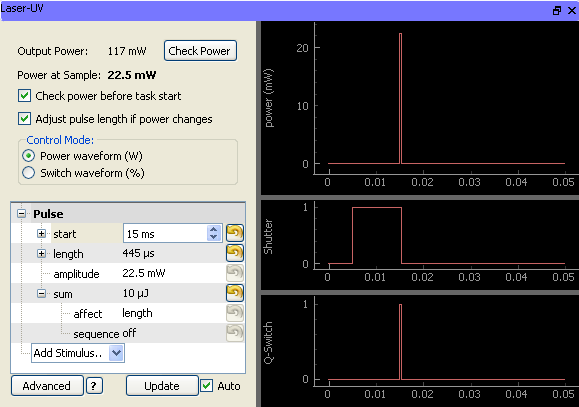
- Calibrated output through a variety of mechanisms:
- Q-switch or shutter-controlled pulses
- Pockel cell attenuation
- Pulse-width modulation
Output calibration accounts for attenuation factors which are dependent on optical pathway (for example, each objective lens may have a different attenuation factor).
Laser device subclasses:
Configuration Options
Example configuration:
Laser-UV:                                               ## A QSwitched laser with an external shutter and photodiode
    driver: 'Laser'
    scope: 'Microscope'
    parentDevice: 'Microscope'
    pulseRate: 100*kHz                              ## Laser's pulse rate
    powerIndicator:                                 ## Here, a we specify a previously defined DAQGeneric device (Photodiode-UV) to
                                                    ##    use to measure the power at the output of the laser
        channel: 'Photodiode-UV', 'Photodiode'      ## photocell channel for immediate recalibration
        rate: 1.2*MHz                               ## sample rate to use when measuring power
    shutter:
        device: 'DAQ'
        channel: '/Dev1/line30'                     ## channel for triggering shutter
        type: 'do'
        delay: 10*ms                                ## how long it takes the shutter to fully open
    qSwitch:
        device: 'DAQ'
        channel: '/Dev1/line29'                     ## channel for triggering q-switch
        type: 'do'
    wavelength: 355*nm
    alignmentMode:
        qSwitch: False                              ## For alignment, shutter is open but QS is off
        shutter: True
    defaultPowerMeter: 'NewportMeter'
Manager Interface
The Laser Manager interface allows the user to control the state of the laser and to calibrate the attenuation of the laser power through the optical path. From the Manager interface the user can open/close the shutter, turn on/off a QSwitch, and on tunable shutters he or she can select the desired wavelength.
If the hardware is configured with a power indicator, the current laser power is displayed. Each time the laser power is measured, the estimated power at the sample plane is calculated using the attenuation measurement for the current optical pathway. In the case of power fluctuation, the laser device can be setup up to alert the user and raise a warning when starting tasks if the laser power is outside the desired range.
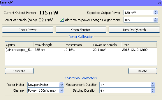
The laser device keeps a set of attenuation factors for each optical path. To calibrate the attenuation factors, the user must place a power meter or photodiode under the microscope objective. If there are multiple lasers or objective lenses, one calibration must be made for each combination. Calibration parameters include:
- Power Meter: Select the device used to measure the power under the objective.
- Channel: Select the channel on the selected power meter. Currently, only one channel is supported, but support for multiple channels is in development.
Measurement Duration: The time over which the average power will be measured.
Settling Duration: The amount of time it takes the selected power meter to arrive at a stable reading. For example, this is long (~4 seconds) for the NewportMeter in this example, but short (~tens-hundreds of ms) for other devices like photodiodes.
When calibrate is clicked, the Laser Manager interface runs an automatic calibration routine:
Data for a “Laser Off” state is collected, where the shutter is closed and the QSwitch off.
- Data for a “Laser On” state is collected, where the shutter is open and the QSwitch on.
- The duration of both data collection tasks is determined by Settling Time + Measurement time.
The data collected during the measurement times of both the “Off” and “On” states is averaged, to measure the power at the sample.
The measured power at the sample is then compared to the power at the output of the laser to calculate the percent transmission through the optical pathway.