Optomechanical devices
The experiments that ACQ4 is designed to handle often involve multiple devices whose spatial relationships to each other must be calibrated, tracked, and reported. For example, a user may wish to collect a set of images from a range of locations across a sample, mark locations for later reference, or direct a scanning laser to specific sites in the sample. To accomplish this, a global coordinate system is used throughout ACQ4 to represent the physical coordinates of the sample. Any recording or stimulation that has a defined spatial relationship to the sample is automatically registered with the global coordinate system. Thus, images and photostimulation data are automatically stored alongside their global position and scale, allowing automatic reconstruction of image mosaics (multiple tiled images).
A broad subclass of devices, referred to as optomechanical devices, represent hierarchically-linked hardware with defined physical or optical relationships to one another and, ultimately, to the global coordinate system. The choice of an appropriate global coordinate system is arbitrary and left to the experimenter, although in systems which use any type of imaging, the global coordinate system is typically chosen to be fixed relative to the imaged subject. Static relationships between devices are specified in the device configuration file, whereas any changes in dynamic relationships (for example, when a motorized stage moves, or an objective lens is changed) will be immediately reflected in the coordinate system transformations between devices in the hierarchy. In most cases, the static configuration is determined and written manually. For more complex relationships, however, automated calibration functions may be used to assist in generating the necessary configuration.
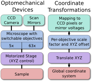
An example optomechanical device hierarchy.
For example, a motorized stage, microscope, and camera may all be linked optomechanical devices. As the stage moves, the global coordinate location of the microscope and camera will shift to reflect this new arrangement. Likewise, changing the objective lens currently in use will change the optical scaling and offset associated with the microscope, which in turn defines the boundaries of the camera sensor relative to the sample. In this example, the scaling of the camera sensor coordinates would be measured manually under different objective lenses by imaging a calibration target or by moving the sample by a known distance. Because all coordinates are represented in 3D, it is also possible to seamlessly and transparently add Z-control such as a motorized focusing mechanism.
The end result is that devices in the optomechanical hierarchy generate data that is registered to the physical coordinates of the sample, and this requires no effort from the user during the experiment as long as ACQ4 is able to record positioning information. The structure of this device hierarchy is entirely user-definable, allowing ACQ4 to work with arbitrary device configurations.
Configuring optomechanical devices
All optomechanical device types (this currently includess cameras, microscopes, stages, and scanners) accept two configuration options that define their relationship to the device hierarchy:
parentDevice: The device to which this device is rigidly connected. If no device is given, then the device is ‘connected’ to the global coordinate system.
- transform: A set of parameters that define the coordinate mapping between this device’s local coordinate system and its parent’s coordinate system (or the global system, if there is no parent).
- position: A list of 2 or 3 values defining a coordinate translation.
- scale: A list of 2 or 3 values that scale the coordinate system.
- angle: An angle of rotation (in degrees)
- axis: A vector defining the 3D axis of rotation. By default, this is set to (0, 0, 1); that is, rotation is around the Z-axis unless otherwise specified.
Each of the transformation parameters is used to construct a matrix M = (Scale * Rotate * Translate) that maps from the local coordinate system of the device to the local coordinate system of its parent.
Example configuration for a camera:
Camera:
    driver: 'PVCam'
    parentDevice: 'Microscope'  # This camera is mounted to the device
                                # named 'Microscope'
    transform:
        position: (0, 0, 50*um) # Camera focal plane is Z-shifted 50 um
                                # relative to other imaging devices
        scale: (1, -1)          # A mirror in the system inverts the camera
                                # image about the y-xis
        angle: 2.3              # Damaged mounting hardware causes the
                                # camera to sit at a 2.3 deg angle relative
                                # to other devices.