Simulated Patch Clamp Amplifier
For demonstration and testing purposes, ACQ4 includes a device that simulates the behavior of a patch clamp amplifier attached to a neuron. To use this device, it is necessary to also define a :ref:’NiDAQ device <userDevicesNiDAQ>’ that has the configuration parameter mock: True (it is not necessary to have a physical DAQ device). This device may be used to test the Patch and TaskRunner modules.
Internally, the neuron and electrode are simulated with a simple Python script (located at acq4/devices/MockClamp/hhSim.py). This script defines a basic Hodgkin-Huxley neuron and a patch electrode with access resistance.
Configuration Options
Example configuration:
Clamp1:
    driver: 'MockClamp'
    simulator: 'builtin'  # Also supports 'neuron' if you have neuron+python
                          # installed. See lib/devices/MockClamp/neuronSim.py.

    # Define two connections to the DAQ:
    Command:
        device: 'DAQ'
        channel: '/Dev1/ao0'
        type: 'ao'
    ScaledSignal:
        device: 'DAQ'
        channel: '/Dev1/ai5'
        mode: 'NRSE'
        type: 'ai'

    # Default holding values.
    icHolding: 0.0
    vcHolding: -50e-3
Task Runner Interface
The task runner interface for the MockClamp is similar to the interfaces defined for AxoPatch and MultiClamp devices.
The left half of this interface consists of three main sections:
A list of operating modes (vc, i=0, ic). The selected clamp mode will be set immediately before the task is executed.
Controls affecting recording from the primary output channel of the amplifier (Scaled Signal).
- Controls that determine the command output:
- Pre-set sets the voltage or current command immediately before the task begins, if the box is checked.
- Holding determines the voltage or current command that will be set immediately after the task finishes. If the box is unchecked, then the current holding value (as indicated in the Manager interface described above) will be used.
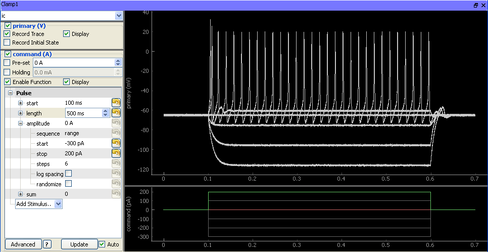
- A function generator that is used to specify the output waveform and sequence parameters.
The right half of the interface holds plot areas for displaying the recorded signal (top) and command signal (bottom).